hey, im looking into making a generator, but i am not 100% on how to wind the coils... do you have any info on that?


hey, im looking into making a generator, but i am not 100% on how to wind the coils... do you have any info on that?

. . . . . . . . . . oh. so you only want to know how to physically wind the coil, nevermind any of the details which would determine coil dimensions, wire gauge, number of turns, type of wire, etc. So the short answer you're looking for is simply to make a wood spool, like this.
yea. thats kinda what i was looking for, but you mentioned paralell wires, ore something like that.
wht do you do with the ends, dose one end just sit idle at the inside of the coil? i thought it fed back to the studs.
now, for the more complex question...how do i calcuate the number of windings, wire gauge, type of wire ect ect... or at least what site do i go to, to find out?
these magnets look like they would make an awsome generator.
<a href="http://www.magnet4less.com/product_info.php?cPath=1_15&products_id=792">h ttp://www.magnet4less.com/product_info.php?cPath=1_15&products_id=792</a>
bump..... any help?

[quote=andrewmason=Originally Posted by rreidnauer
yea. thats kinda what i was looking for, but you mentioned paralell wires, ore something like that.
wht do you do with the ends, dose one end just sit idle at the inside of the coil? i thought it fed back to the studs.
now, for the more complex question...how do i calcuate the number of windings, wire gauge, type of wire ect ect... or at least what site do i go to, to find out?
these magnets look like they would make an awsome generator.
<a href="http://www.magnet4less.com/product_info.php?cPath=1_15&products_id=792" style="color: #027ac6; text-decoration: none;">http://www.magnet4less.com/product_info.php?cPath=1_15&products_id=792</a>
[\quote]sorry, but it looks like you (possibly inadvertently) were rude to Rod. I guess we'll all just have to wait for his "how to make linear flux alternators" book now...
I have been trying to fallow the making of your magnetic power generator. How is it coming along? I am interested in seeing completion and put into practice. Please continue this thread.
JO D
I don't know what it is, but I've GOT to have one!
Please .... tell us the secret of making linear flux alternators Rod!
OK, I have simmered down :-) so I'll continue with the tutorial.
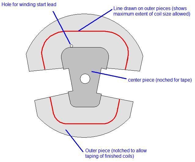
Alright, so now, you should know what size coils you can have, you can make a coil winder. The way I did it was to make cardboard template from my drawn coil layout. The winder is made of a 3 piece wood sandwich. The center piece is the shape of your coil hole. The outer pieces are larger than your wound coil, but should be marked where the coil shouldn't get any bigger, so you don't wind too much and make the coil too large. (I'll take a picture of mine when I'm back at work on Monday) There are also two cutout's in the winder that allow you to tape the coil legs once wound while still in the winder, so they don't spring apart when you go to remove them. Some people just have their wire start in the tape notch, but I prefer a separate hole. This allows for the transition between coil layers to happen at the outside of the coil, and keeps the legs perfectly parallel and dense. Here's a rough sketch of what it should look like:
Now, you need to get into the really difficult mathematical portion of the build. This math will help determine your number of windings and wire size. So many things come together at this point. I'll try to work through them one at a time. First, you need to decide on several factors. What voltage will you be using? What maximum wattage from the windmill do you want? What size windmill do you wish to build? (which also effects windmill speed)
(Ugh, my head is spinning just trying to remember all the steps required. Bear with me)
OK, first. Go to this site: http://warlock.com.au/tools/bladecalc.htm Select imperial units if working here in the States, leave number of blades as 3, TSR as 7. Change blade efficiency to 0.35. Select a reasonable windspeed for where you'd like to reach maximum output. (I prefer 20 MPH, but you may like 15) Play with the blade radius numbers and hit calculate, and note the wattage. The wattage calculation shown is what is obtainable from the rotor, NOT necessarily what the generator will put out. Try different blade radius-es until you get your chosen wattage you'd like to produce. Now change the windspeed to 8. This is a good "cut in" speed, the speed at which a windmill's voltage rises to meet the voltage of your battery bank and begin charging. Much slower, and you risk stalling the rotor blades under a charging load. The RPM is what we are interested in. With this RPM, we can begin to calculate the number of winding turns per coil. OK, headache time. Knowing you battery bank voltage, you will use this calculation:
Target DC voltage + 1.4v rectifier loss + line loss x 0.7 AC to DC gain / 1.73 star gain / number coils in one phase = AC volts per coil. (LOL, I know what you're thinking)
Let's break it down. Let's say our Target battery bank voltage will be 24v. Add to that 1.4 volts. (that is the voltage that will be lost to the rectifier which converts AC to DC) Also add whatever your expected voltage drop will be between your windmill and batteries. Here's a calculator: http://www.csgnetwork.com/voltagedropcalc.html So for example let's say 24v system, 1000 watt generator, that's 41 amps (watts divided by volts) and lets say it's a 50 foot run of #8 cable. That's 3.1 volts line loss added to the above calculation. So we are up to 28.5 VDC. Now we get some benefits, converting AC to DC actually increases voltage, so we multiply our 28.5 by 0.7 for 19.95 VAC, and we divide by 1.73 for phase interaction within the generator, for a value of 11.53 and divide again by the number of coils in a phase, which in a three-phase, nine-coil generator is three, so that gives us 3.84 AC volts per coil. This is the required voltage of a single coil at the RPM generated at our windspeed cut in point of 8 MPH. (I told you it was going to be a headache!!)
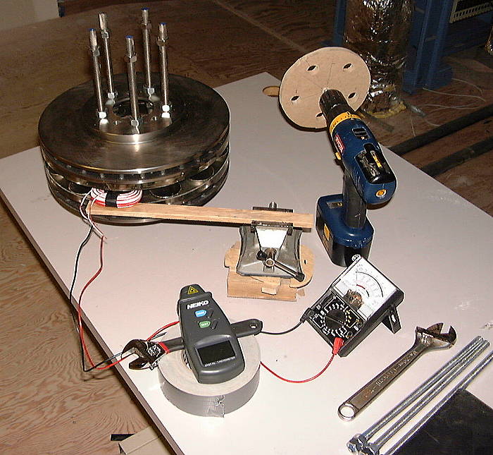
At this point, you should really have your magnet rotors built, because you'll need to get data with a test coil, since magnet's flux strength will differ between shapes and sizes. You'll need a few things for the test. A test coil. (I simply used some inexpensive 20 ga "doorbell" wire) A tachometer (I used a cheap laser version I got off ebay) An analog (not digital) voltmeter, and something to rotate your rotor up to "cut in" RPM. (I used a battery drill and made a simple adapter to fit over the threaded rods) My first coil, I just wound like 50 turns and ran a test.
From that test, I turned the rotor at cut in speed, and read the voltage coming off the coil. I took the voltage value, divided by the number of turns to get volts per turn. Now, knowing that our hypothetical target voltage per coil above was 3.84, you divide that by the volts per turn and wala, you have the required number of turns per coil.
Next, determining coil wire size and deciding between single or parallel conductors, but time for another typing break.
Alright, back to it.
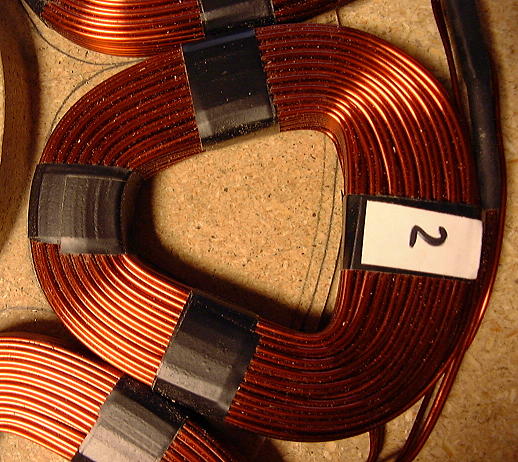
So now you know how many turns you require, and you know the dimensions of your coils. Now you need to figure out how to pack the maximum amount of wire into your coils that the number of turns and dimensions allow. The reason is, you want to get the lowest resistance possible, because with higher resistance, not only are you loosing potential charging energy, but that resistance gets converted to heat, and yes, it's possible to burn up your generator. You'd think just going with the biggest gauge wire you can fit in the number of turns required would be best, but it's not, because the round cross-section of wire allows for a lot of wasted space between wires. The smaller the wire, the less wasted space. So if you can find a wire gauge with half the cross-section area and use two of them in parallel, you can get more copper in and less wasted space. (even 3 or 4 parallel strands are a possibility) So, with multiple conductors making up more copper and less wasted space for the same amount of turns, that can only mean you have less resistance in your coil. The down side is, they are more difficult to wind and keep in a neat, tight, parallel configuration. Referring back to my earlier sketch, I say your start lead(s) begin at the hole, you'd wind counter-clockwise. This is because as you complete one turn, the wire(s) move over to start the second turn. This action will force parallel strands to not lay together during this transition, and you end up with a wider coil in this spot. You can probably see in this pic that the outer portion of the coil is wider than the rest.
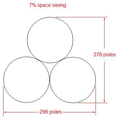
Ideally, you'd want your coil winder just wide enough to fit "X" number of conductors per layer, plus one half conductor. This is because as you start the next layer, the wires will lay in between wires of the previous layer, filling the maximum amount of space. With the secondary layer of wires in between wires of the previous layer, you save about 7% in height, compared if they were stacked directly on top of one another. Another sketch to clarify.
If your winder isn't quite right, you can sandwich in a bit of cardboard to get a width that makes it work out. Also, if winding multiple conductors, I found that while winding and reaching the end of one layer, the best way to get maximum fill is to put a half twist in the pair, so whichever conductor was the lead conductor in the first layer, will also be the lead conductor of the next layer. See if this animation helps visualize the concept.
So, what size conductors should you use? Well, that takes some figuring. The best place to start is finding out what the diameter of different gauge wires are, and figuring out how many conductors you can get in width and depth of your coil legs, and see if the total adds up to the number of turns you require. http://en.wikipedia.org/wiki/American_wire_gauge has a chart of wire diameters for various wire gauges. Keep in mind that epoxy coated magnet wire is going to be a little bigger than the bare wire figures given, so add approximately 0.002"
Next post, putting it all together.
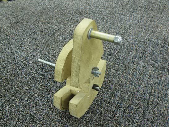
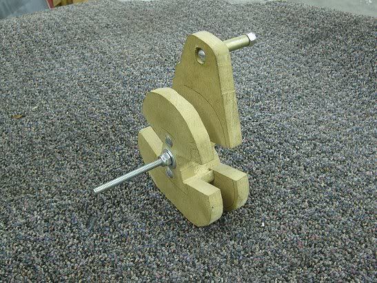
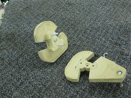
Here are a few pictures of my winder. The long screw would get clamped in a vice or B&D Workmate bench. The removable end-plate allows you to remove the coil after winding and taping.
1 your "battery bank voltage" is nominal. my lead acid battery in my car charges @ 14.4 V, so 2 of them would be 28.8 V.
Aside from that, the charge/discharge voltage difference for Ni-Fe batteries are very large, I believe 1.71 V/cell for charge, and have a nominal voltage of 1.2 V. How do you deal with this very high disparity.
I like Ni-Fe, cuz I can get used cells super cheap, they are pretty easy to refurbish, and the high charging voltage allows you to simply hook up the cells to your solar array, without a charge controller (10 x 1.71 = 17.1V, so I won't overcharge them).
topping them off with a generator will be difficult, though, as most chargers operate at ~14.4V, which won't even touch the requirements of the bank. Also, I am a bit scared of burning out my 12V electronics @ 17-18V. I may use only 9 cells (I have a line on pallets of 80 AH cells), which would lower the charge voltage to 15.39V and would give a smaller nominal voltage of 10.8V. Anyway, I am thinking to make one of these specifically to run off a diesel genset to charge my batteries. Any thoughts?
-peter
Alright, first off, 14.4 volts is not a nominal voltage for a lead-acid "12 volt" battery. An at-rest fully charged 12v battery's voltage is 12.70v, and when discharged to 70% capacity, it's voltage is 12.36v (again, at-rest) OK, so what's with the 14.4 stuff then, right? Well, that is a case of overvoltage being delivered to the battery to drive the amperage into it. A battery is very similar to a water tower. With a water tower, you are going to need more PSI to pump water into the tower, than the tower is already pushing back with. And, the higher your pump pressure, the faster the water will go in. A battery is the same way, except its "electrical pressure" (voltage) instead of water pressure. Realistically, a car's regulator just working to maintain a constant 14.4 volts is actually quite hard on a battery (hence one reason car batteries usually don't last long) but it is the simplest solution in the automotive world. (hurry and get it charged up so it's ready for next use)
You're jumping ahead of me a little here, but a permanent magnet, axial flux generator's voltage increases linearly with RPMs. So if you reach a "cut-in" voltage of say 12.5 at 100 RPM, you then know that the generator will reach 25 volts at 200 RPM. (open circuit) Now, when the generator is directly connected to the battery, a phenomenon occurs, that the battery bank itself will regulate the voltage. (at least up until the battery reaches capacity, then voltage will rise quickly, heat up, and boil off electrolyte if left unchecked) So what happens, is the overvoltage being produced by the generator gets converted into amperage, and you see that case of higher voltage pressure, faster charging pattern. (I'll get into the math of how to calculate it in upcoming posts) This kind of answer's you second question. You really don't have to account to much for a voltage difference. If the bank voltage is a little higher (say near full charge) vs a low battery, the windmill will just start charging at a slightly higher RPM.
I'm not real well versed on the Nickle-Iron "Edison" batteries, but I do know they handle over-discharged states without damage. I can see your worries of sending too much voltage to your appliances while the windmill would be charging, driving your 12v Ni-Fe bank up to 17v (if that's what they really charge at) Sure, you can use 9 cells and simply account for the voltage difference when designing your cut-in speed voltage. Heck, if you have it wrong, it just means your cut-in will occur at a slightly higher or lower windspeed. (not a real big deal unless you get too slow a windspeed cut-in) So if you planned your windmill for 9 cells, but didn't like the voltage (say your 120v inverter drops out under load) and you added a 10th cell, your cut-in would occur at approx 1/10th more than the 9 cell cut-in speed, so say the original planned 15.4v at 8 MPH, it would now be 17.1v at 8.9 MPH. (15.4 / 8 * 8.9 = 17.1)
The thing with wind and hydro is, you don't have a way to throttle back the incoming power like you do in a car with induction magnetic field control regulators. And you can't just disconnect the battery from the generator either, as it will unload the generator, and without that electrical resistance the generator will run away and self destruct. You have only one option, and that is a dump-load controller which, when the battery is full and voltage begins to rise, the dump-load controller will have a voltage setpoint, where it will close a switch that is connected to a 12 volt load (heating elements?) of at least as much amperage that your windmill is capable of putting out. The controller is a little more complicated than that, but it's roughly how it functions.
I'm not sure about your diesel powered charging system for the Ni-Fe batteries. I have no idea how they'd respond to an automotive alternator. You'd have to play around with it and make sure it doesn't overcharge and boil your electrolyte. (shouldn't if 9 cells is 15.4v, but I don't know)
I have almost no wind at my land. Someday, I may build a 50m tower at the top of the mountain and get a bit of what wind there is, but the mountain is out of range of my current location. Anyway, I don't want to have an "automotive alternator" but a linear flux alternator (which I can tune myself), I will have to determine how to regulate the rpms.
Thanks again.
-Peter
<a href="http://www.magnet4less.com/product_info.php?products_id=792">http://www.magnet4less.com/product_info.php?products_id=792</a>
it sounds logical that the more magnets i can put on my rotor, the more efeicent it will be (this is obvously up to a certain point, a magnet 1/2" wide wouldnt create a strong enough magnetic field across the stator gap to work effectively)
so using these wedge magnets i can get more magnets in the same space.... now, with this i would be going from your example using 12 magnets and 9 coils to my 16 magnets and 12 coils... still maintaning the 4;3 ratio. do you see any issues with this.
only thing i can think of is that coils are going to have to be on the small side.
and for number sake, i have thinking of doind a 15ft dia prop.... but i am also thinking of more than 3 blades, but i havent looked into it allot.
here is some monthly average wind speeds for where i currenly am in southern california.
it is broken down monthly, jan-dec, and the last is anually, a note, this data was collected from a automatic weather station from 1996-2006.
TWENTYNINE PALMS EAF |KNXP|1996-2006| 7.0 7.8 8.5 10.4 9.5 9.7 8.3 7.8 6.9 6.7 6.6 6.9 | 8.0
and for anyone interested here is the page.
<a href="http://www.wrcc.dri.edu/htmlfiles/westwind.final.html">http://www.wrcc.dri.edu/htmlfiles/westwind.final.html</a>
to the series rod? You should seriously just write a book. I'd review it for you for the low low commission of a signed first edition.
-Peter
Oops, I forgot about this. Yea, I'll get back to it here shortly.
bump
Ugh, yea, I know. I'm slacking. I've just been burried with al kinds of things. I just got in from 12 hours on the road, so I'm in no state of mind for another chapter. I'll try to fit one in here sooner or later.
...I'm looking at you, Rod!
Here we go.
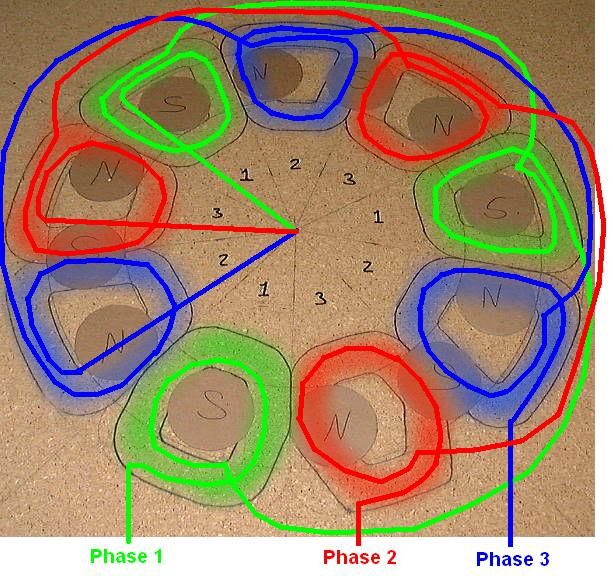
So now if all went well, you should have wound 9 identical coils, and now they need to be wired together. To do that please refer to the nightmare of a sketch below.
I color coded each phase in hopes it makes it easier to understand how it's wired. There are a few important points to note. Most important is that all the coils (at least on a three phase turbine) need to be wound in the same direction. Whether that's clockwise or counter-clockwise doesn't matter, just as long as they are all the same. If you had one coil wound opposite the other two, it would cancel out one of the correct coils, severly limiting output. In addition, all three groups of three coils must also be in the same wind direction, or you'll end up with interaction problems, also severly limiting output. So, just make sure all your coils are laid in the same direction, and you'll have no problems.
So tying coils together, you need to wire the "end" lead of the first coil, to the "start" lead of next coil in the proper phase. (that being every third as shown in the sketch above) and do the same from second coil to the third. When you get to the end lead on the third coil of a phase, you will be connecting it to the end leads of the third coils of the other two phases. (you don't need to take them to the center to terminate them. I just drew it that way to clarify) The start leads of the first coil in each phase are your output leads. (hopefully the sketch makes more sense than the explanation)
So to physically tie the leads together, I prefer an uninsulated crimp sleeve (or a piece of copper icemaker tubing if the wires are too big for common crimp sleeves) To do this requires a few steps for a long lasting, trouble-free connection. First, with the coils positioned as they will be in the stator, (and I prefer to do it right in the stator mold, but it's not necessary) trim the wires to length between coils. (if using icemaker line, have the wires overlap instead of butting together) You need to remove the epoxy insulation from the magnet wire, and the best way to do this is to take a torch and litterally burn it off where you'll be making the connections. Then take some sandpaper to remove residual epoxy and shine up the wire. Before placing the leads in the crimp sleeve, slide a piece of heat shrink tubing over one of the leads and slide out of the way. Put the leads in the crimp sleeve and crimp. I highly recommend soldering the connection as well, and it's best to use a silver solder. Afterwards, slip the heatshrink over the connection and heat it to shrink. Repeat for the rest of the connections, including the end leads of the three phases. There should be a total of seven connections to make.
How to handle the output leads is up to the individual. Most people would just have the wires exit the mold, and connect to a screw drilled through the stator's edge. I prefer to embed brass toilet bolts in the stator, and solder the leads to the bolts. Once you have the coils wired, now is a great time to find a way to temporarily secure them so you can move them as a group. An easy way to do this is to take pieces of fiberglass laying across the legs of two coils, and use CA glue to bond the two together. Do this to all nine places, then carefully flip the coils over, and do the same to the other side. At this point, the coils will be a pretty rigid, single mass.
Next, stator mold construction.
The stator mold is pretty straight forward compared to everything mentioned previously. Size is simple to determine. The inside opening needs to be large enough to allow the rotor threaded rods to pass through, and the outside diameter needs to be large enough to allow drilling mounting holes in it, outside the area where the coils are embedded. Meanwhile, thickness is determined by the coils themselves, only making the stator slightly thicker than the coils themselves.
I just picked up a three 2'x2' pieces of particle-board for my mold, at the local big-box store, to build up a three layer sandwich. The top and bottom layers don't involve much work, but the middle layer does get significant modifications. OK, to each their own, the following is how I made mine. If you come up with another way to achieve similar results at reduced costs, great!
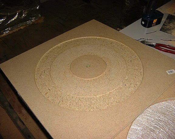
I found center of one of the boards, and took a makeshift circle compass to mark both the inside and outside diameters of where I was going to need to remove material for the coils. I then laid that piece on top of one of the other boards. I screwed the top board to the bottom board (countersinking the heads) and careful NOT to put any screws where I needed to remove material. I then drilled a 1/4" hole dead center in the board, and from the bottom up, placed a 1/4-20 bolt long enough to reach through three boards and still have enough length to put on a nut. At this point I was ready to route out my mold, but required two items. One was a circle jig. (you can buy these, but I just made my own from some 1/4" luan plywood) The other item was a tapered router bit, which allows easier extraction of your stator from the mold. A straight vertical raised-panel bit works perfectly.

I set my circle jig to route out the inner diameter edge, and began to plunge cut the bit until it was as deep as the coil thickness. I cut all the way around, then did the same for the outer diameter. (in my case, my coils were a little thicker than the boards, so I ended up routing out a bit more in the lid. Don't do this, instead route deeper into the bottom board if need be. You'll have less problems with trapped air later)
What not to do: (domed lid)
I finished up by drilling a 1/4" hole dead center in the top board, and also drilling holes where I want the power output lugs (the brass toilet bolts) to go, and coating the inside of the mold with mold release wax.
Next episode, finishing up the stator.
All my bad forum habits I learned from LHN
Rod Reidnauer
Class of Apr. 9-10, 2005
Thinking outside the vinyl sided box
Hey Rod, If that stator mold has got ya worried, I have a fungus nut who can identify it for you. Ha ha.
LHN, your fungus is talking now? JK... Rod, great to see that the thread is back up and running!
Peter, working the dream
www.youtube.com/stressman79
photobucket/site address: http://s319.photobucket.com/albums/mm471/stressman79/
Rod, why is one coil shaped differently on the bottom right?
Peter, working the dream
www.youtube.com/stressman79
photobucket/site address: http://s319.photobucket.com/albums/mm471/stressman79/
Actually the two bottom ones are drawn differently. I was experimenting with different shapes to see if I could find any advantages, but stuck with how the majority were drawn.
All my bad forum habits I learned from LHN
Rod Reidnauer
Class of Apr. 9-10, 2005
Thinking outside the vinyl sided box
Peter, your PM inbox is full. I believe these are the magnets I ordered: http://www.magnet4less.com/product_i...roducts_id=162
All my bad forum habits I learned from LHN
Rod Reidnauer
Class of Apr. 9-10, 2005
Thinking outside the vinyl sided box
 Posting Permissions

 Reply With Quote
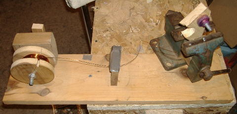

Bookmarks