


Ha, well, since this thread has become active again, I may as well share some of the progress I've been making. So here's some pics of the alternator construction.
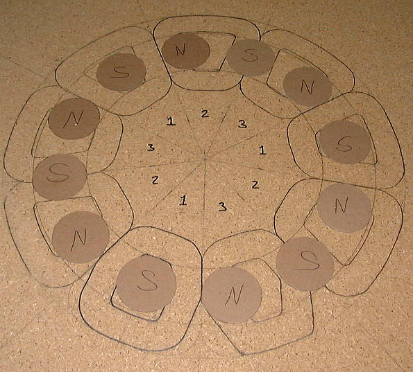
Stator layout with magnet placement visualization. You can see I've been playing with different coil shapes. I've changed my mind at least three times already, including once today!
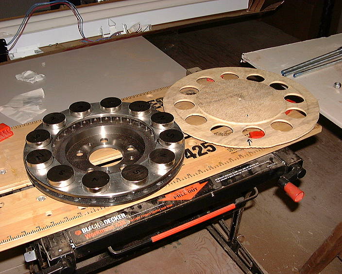
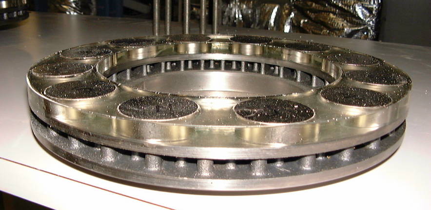
Magnets glued onto rotors, and template for setting magnets. At this point, the rotors are VERY dangerous to handle. Each magnet by itself has 87 lbs. of pull, together it's 1044 lbs, and with the flux conductance of the rotor, it's even higher to a value I'm unable to determine, but it could be as high as double, and that's only one rotor!!!! Needless to say, if you got your fingers between the rotor and some heavy steel, or the other rotor, you can kiss them fingers goodbye. It would squeeze them clean off!!!! :shock: :shock: :shock: :shock:
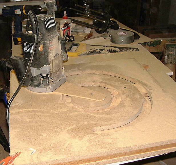
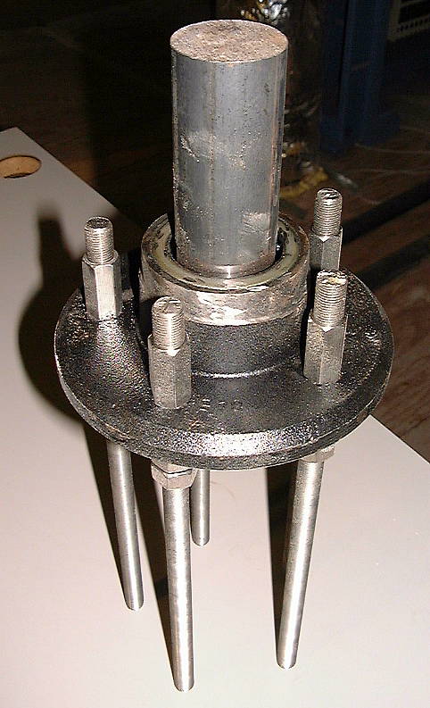
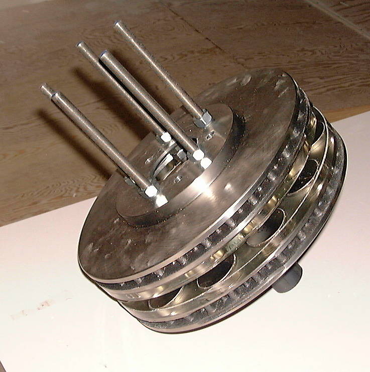
And this is cutting the mold that will make up the stator drawn in the first picture. You can see the hub assembly laying in the background.
That's about where I'm at. More to come.

 Reply With Quote
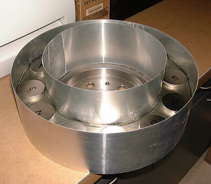

Bookmarks